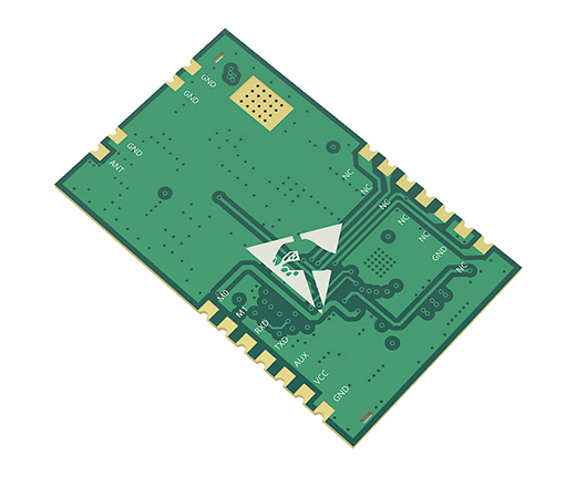
| Serial number | Pins | Pin Direction | Remarks |
| 1 | GND | Input | Module Ground |
| 2 | GND | Input | Module Ground |
| 3 | VCC | Input | Module power supply positive reference, voltage range: 4.5 to 15V DC |
| 4 | VCC | Input | Module power supply positive reference, voltage range: 4.5 to 15V DC |
| 5 | RESET | Input | Module reset pins |
| 6 | AUX | Output | Used to indicate the module operating status; user wakes up the external MCU and outputs low during power-on self-test initialization evel; (can be suspended) |
| 7 | TXD | Output | TTL serial output, connected to the external RXD input pin; |
| 8 | RXD | Input | TTL serial input, connected to the external TXD output pin; |
| 9 | M1 | Input (very weak pull-up) | and MO work together to determine the 4 modes of operation of the module (not suspended, grounded if not in use) |
| 10 | MO | Input (very weak pull-up) | Works with M1 to determine the 4 operating modes of the module (not suspended, can be grounded if not in use) |
| 11 | GND | Input | Module Ground |
| 12 | GND | Input | Module Ground |
| 13 | ANT | Output | Antenna interface (high frequency signal output, 50 Ohm characteristic impedance) |
|
|
|
|
| 14 | GND | Input | Module Ground |
| 15 | GND | Input | Module Ground |
| 16 | GND | Input | Module Ground |
| 17 | GND | Input | Module Ground |
| 18 | GND | Input | Module Ground |
| 19 | GND | Input | Module Ground |
| 20 | STATE | Output | Module status indication output, if not used suspension processing is sufficient. |
| 21 | 485-EN | Input/output | The enable control pin of the external 485 chip can be used if it is not suspended for processing. |
| 22 | NC | - | No need to care, overhanging treatment. |
| 23 | NC | - | No need to care, overhanging treatment. |
| 24 | NC | - | No need to care, overhanging treatment. |
| 25 | SWDIO | - | No need to care, overhanging treatment. |
| 26 | SWCLK | - | No need to care, overhanging treatment. |
| 27 | GND | Input | Module Ground |
| 28 | 3.3V | - | No need to care, overhanging treatment. |