| Hardware parameter | Value | Remark |
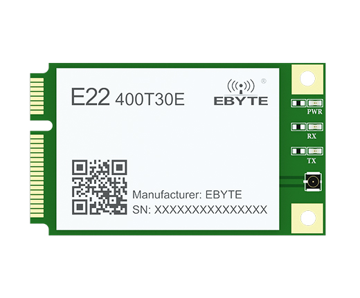
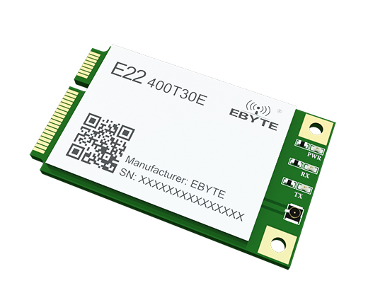
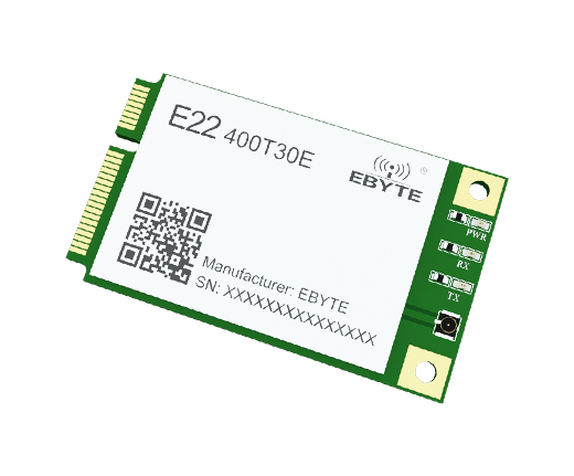
| Dimensions | 30 * 51 mm |
|
| Antenna form | 1st generation IPEX | Equivalent impedance is about 50Ω
|
| Communication Interface | UART/RS485/RS232/USB | The communication interface only supports the simultaneous use of one |
| Packaging method | In-line |
|
Electrical
parameters | Min | Typ | Max | Unit | Remark |
| Voltage | 3.2
| 5.0 | 5.5 | V | ≥5.0V can guarantee the output power More than 5.5V permanently burns the module |
Communication
level | - | 3.3 | - | V | It is recommended to add level shifting when using 5V TTL. |
| Emission current | -
| 650 | - | mA | Instantaneous power consumption
|
| Receive current | - | 17
| - | mA
|
|
| Sleep current | - | 1.5 | - | mA | Software shutdown |
Operating
temperature
| -40 | 20
| +85 | ℃ | Industrial grade design |
Working humidity
| 10 | 60
| 90 | % |
|
Storage temperature
| -40 | 20
| +125 | ℃ |
|
| RF parameters | Value | Remark |
| working frequency | 410.125~493.125MHz | Support ISM band
|
| Transmit power | 30 dBm | -
|
| Acceptance sensitivity | -147dbm
| Air rate 2.4 kbp |
| Air rate | 2.4k~62.5kbps | User programming control
|
| Measured distance | 10km
| Clear and open environment, antenna gain 5dBi,antenna height 2.5 meters, air rate 2.4kbps
|

Pin No.
| Item
| Direction | Description |
| 1 | TO | output | Used to indicate the working status of the module; the user
wakes up the external MCU , and outputs a low level during
the initialization of the power-on self-test; (can be suspended) |
| 2 | VCC | Input | Power input 5.0V |
| 3 | M0 | Input
( very weak pull-up ) | Cooperate with M1 to determine the 4 working modes of the
module (not floating, if not used, it can be grounded) |
| 4 | GND | - | power reference ground |
| 5 | Ml | Input
( very weak pull-up ) | Cooperate with M0 to determine the 4 working modes of the
module (not floating, if not used, it can be grounded) |
| 6 | NC | - | -
|
| 7 | NC | -
| -
|
| 8 | NC | -
| -
|
| 9 | GND | -
| power reference ground |
| 10 | SMD_DI0 | input /output | Program download data interface ( the module needs to be
reset or erased before SWD programming ) |
| 11 | RXD | input | TTL serial port input, connect external TXD output pin |
| 12 | swD_CLK | input /output | Program download clock interface ( the module needs to be
reset or erased before SWD programming ) |
| 13 | TXD | output | TTL serial port output, connect external RXD input pin |
| 14 | NC | - | - |
| 15 | GND | - | power reference ground |
| 16 | NC | -
| -
|
| 17 | NC | -
| -
|
| 18 | GND | -
| power reference ground |
| 19 | NC | - |
|
| 20 | NC | - | power reference ground |
| 21 | GND | - | power reference ground |
| 22 | RESET | input | The input low level module enters the hardware reset state, and
the input high level module recovers the normal working state.
This function is used for the reset operation in emergency |
| 23 | NC | - | -
|
| 24 | VCC | input | Power input 5.0V |
| 25 | NC | - | -
|
| 26 | GND | - | power reference ground |
| 27 | GND | - | power reference ground |
| 28 | NC | - | -
|
| 29 | GND | - | power reference ground |
| 30 | NC | - | -
|
| 31 | NC | - | -
|
| 32 | NC | - | - |
| 33 | NC | - | -
|
| 34 | GND | - | power reference ground |
| 35 | GND | -
| power reference ground |
| 36 | USB_D- | input /output | D- of other external USB devices |
| 37 | GND | - | power reference ground |
| 38 | USB_D+ | input /output | D+ connected to other USB devices |
| 39 | VCC | input | Power input 5.0V |
| 40 | GND | - | power reference ground |
| 41 | VCC | input | Power input 5.0V |
| 42 | NC | - | -
|
| 43 | GND | - | power reference ground |
| 44 | NC | - | -
|
| 45 | RS232_RXD | input | External TXD of other RS232 devices |
| 46 | NC | - | -
|
| 47 | RS232_TXD | output | RXD connected to other RS232 devices |
| 48 | NC | -
| -
|
| 49 | RS485_A | input /output | A terminal connected to other RS485 devices |
| 50 | GND | - | power reference ground |
| 51 | RS485_B | input /output | Connect to the B terminal of other RS485 devices |
| 52 | VCC | input | Power input 5.0V |