| No. | Pin | Pin Direction | Remarks |
| 1 | GND | Input | Module ground wire |
| 2 | GND | Input | Module ground wire |
| 3 | VCC | Input | Module power positive reference, voltage range: 4.5 ~ 15 V DC |
| 4 | VCC | Input | Module power positive reference, voltage range: 4.5 ~ 15 V DC |
| 5 | RESET | Input | Module reset pin |
| 6 | AUX | Output | Used to indicate the working status of the module; the user wakes up the external MCU, and outputs a low level during the power-on self-test initialization period ; (can be left floating) |
| 7 | TXD | Output | TTL serial port output, connected to external RXD input pin; |
| 8 | RxD | Input | TTL serial port input, connected to external TXD output pin; |
| 9 | M1 | Input (very weak pull-up) | Cooperate with M0 to determine the 4 working modes of the module (cannot be left floating, can be grounded if not used) |
| 10 | M0 | Input (very weak pull-up) | Cooperate with M1 to determine the 4 working modes of the module (cannot be left floating, can be grounded if not used) |
| 11 | GND | Input | Module ground wire |
| 12 | GND | Input | Module ground wire |
| 13 | ANT | Output | Antenna interface (high frequency signal output, 50 ohm characteristic impedance) |
| 14 | GND | Input | Module ground wire |
| 15 | GND | Input | Module ground wire |
| 16 | GND | Input | Module ground wire |
| 17 | GND | Input | Module ground wire |
| 18 | GND | Input | Module ground wire |
| 19 | GND | Input | Module ground wire |
| 20 | STATE | Output | Module status indication output, if not used, just leave it unconnected |
| 21 | NC | - | No need to care, floating |
| 22 | NC | - | No need to care, floating |
| 23 | NC | - | No need to care, floating |
| 24 | NC | - | No need to care, floating |
| 25 | NC | - | No need to care, floating |
| 26 | NC | - | No need to care, floating |
| 27 | GND | Input | Module ground wire |
| 28 | NC | - | Floating |
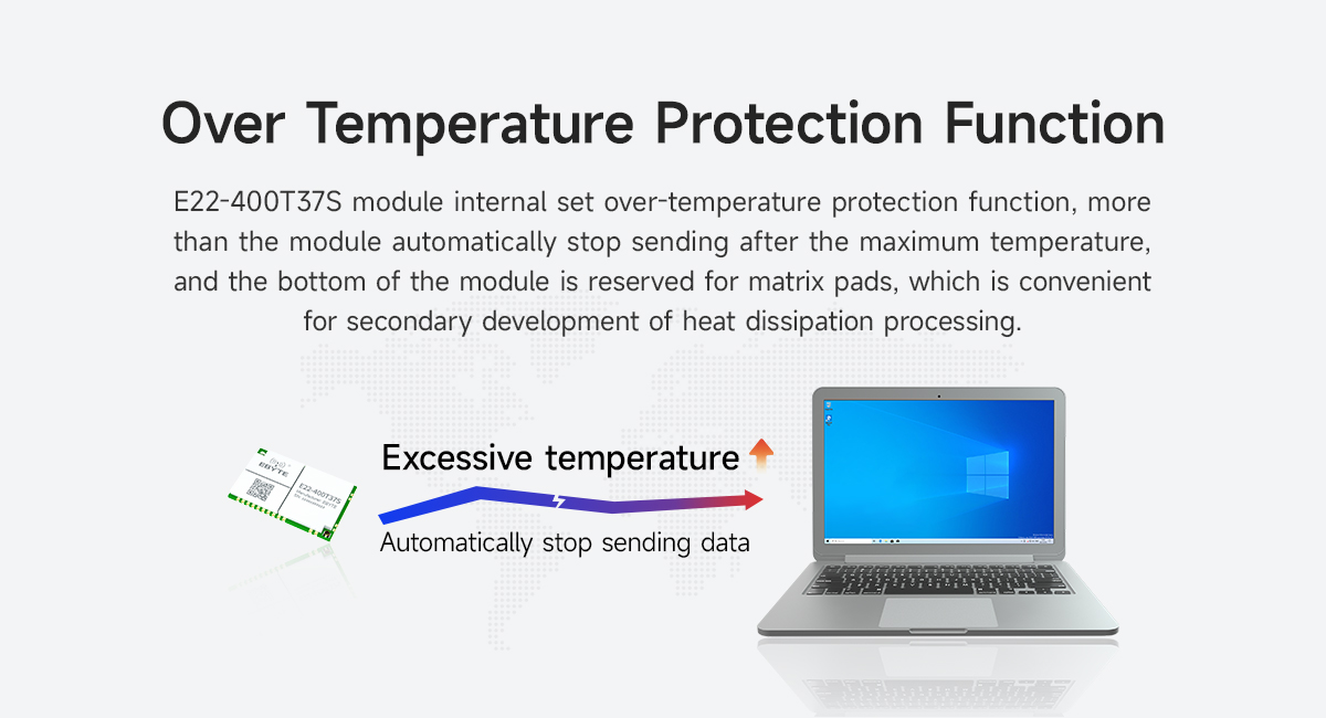
| 29 | NC | - | The bottom of the module is reserved with matrix solder pads. Users need to ground them to assist in the heat dissipation of the module. For detailed dimensions, please refer to the PCB packaging diagram in the relevant download section of the Ebyte official website. |


