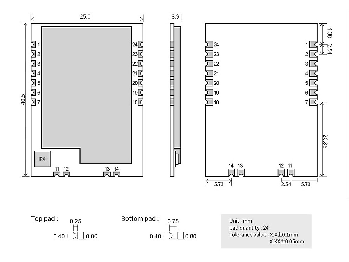
| Pin No. | Pin Name | Pin Direction | Pin Function |
| 1 | GND | Input | Module ground |
| 2 | VCC | Input | Module power positive reference, voltage range:3.3~5.5V DC |
| 3 | AUX | Output | Used to indicate the working status of the module; |
| For user to wakes up the external MCU and it outputs low level during power-on self^check initialization; (can be left floating) |
| 4 | TXD | Output | TTL UART outputs, connects to external RXD input pin. |
| 5 | RXD | Input | TTL UART inputs, connects to external TXD output pin. |
| 6 | Ml | Input (weak pull-up) | Work with MO to decide 4 working modes of module (not float, if not used: could be grounded). |
| 7 | MO | Input (weak pull-up) | Work with Ml to decide 4 working modes of module (not float, if not used: could be grounded). |
| 11 | ANT | Output | Antenna interface (High frequency signal output, 50 ohm characteristic impedance ) |
| 12 | GND | - | Fixed ground |
| 13 | GND | - | Fixed ground |
| 14 | GND | - | Fixed ground |
| 18 | NC | - | NC |
| 19 | NC | - | NC |
| 20 | NC | - | NC |
| 21 | NC | - | NC |
| 22 | RESET | Input | Module reset pin, low level trigger, it is recommended that customers use a single chip microcomputer connection, reset processing and resume work in unexpected situationst) |
| 23 | GND | - | Fixed ground
|
| 24 | NC | - | NC |


