| 1 | GND | - | Ground, connect to power reference ground |
| 2 | GND | - | Ground, connect to power reference ground |
| 3 | GND | - | Ground, connect to power reference ground |
| 4 | GND | - | Ground, connect to power reference ground |
| 5 | DIO3 | - | Configurable universal IO port (see llcc68 manual for details) |
| 6 | RXEN | input | RF switch receive control pin, connect external MCU IO, high level effective |
| 7 | TXEN | input | RF switch emission control pin, connected to external MCU IO or dio2, high level effective |
| 8 | DIO2 | Input / output | Configurable universal IO port (see llcc68 manual for details) |
| 9 | VCC | - | Power supply, range 1.8V ~ 3.7V (it is recommended to add ceramic filter capacitor externally) |
| 10 | GND | - | Ground, connect to power reference ground |
| 11 | GND | - | Ground, connect to power reference ground |
| 12 | GND | - | Ground, connect to power reference ground |
| 13 | DIO1 | Input / output | Configurable universal IO port (see llcc68 manual for details) |
| 14 | BUSY | output | For status indication (see llcc68 manual for details) |
| 15 | NRST | input | Chip reset trigger input pin, low level effective |
| 16 | MISO | output | SPI data output pin |
| 17 | MOSI | input | SPI data input pin |
| 18 | SCK | input | SPI clock input pin |
| 19 | NSS | input | The module chip selection pin is used to start a SPI communication |
| 20 | GND | - | Ground, connect to power reference ground |
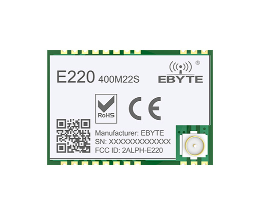
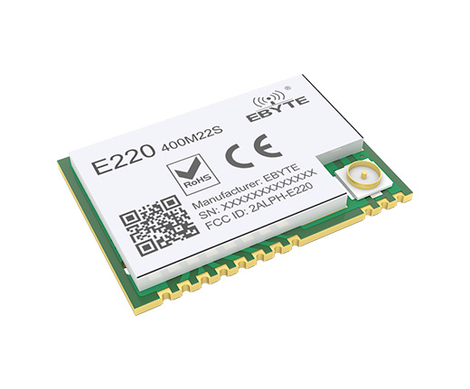
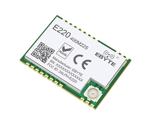
| 21 | ANT | - | RF interface, stamp hole |
| 22 | GND | - | Ground, connect to power reference ground |