| Main Parameters | Value | Remarks |
| Min. | Max |
| Power supply(V) | 0 | 5.5 | Voltage over 5.5V will cause permanent damage to module |
| Blocking power(dBm) | - | 10 | Chances of burn is slim when modules are used in short distance |
| Operating temperature(℃) | -40 | +85 | Industrial grade |
| Main Parameters | Value | Remarks |
| Min. | Typical | Max |
| Operating voltage(V) | 2.3 | 5.0 | 5.5 | ≥5.0 V ensures output power |
| Communication level(V) | - | 3.3 | - | For 5V TTL, it may be at risk of burning down |
| Operating temperature(℃) | -40 | - | 85 | Industrial design |
| Operating frequency(MHz) | 410.125 | 433.125 | 493.125 | Support ISM band |
| TX Current(mA) | - | 110 | - | Instant power consumption |
| RX current(mA) | - | 12 | - | - |
| Sleep current(μA) | - | 2 | - | Software is shut down |
| Max Tx power(dBm) | 21.5 | 22.0 | 22.5 | - |
| Receiving sensitivity(dBm) | -146 | -147 | -148 | Air data rate is 0.3 kbps |
| Air data rate(bps) | 2.4k | - | 62.5k | Controlled via user’s programming |
| Main parameter | Description | Remarks |
| Distance for reference | 5km | Test condition:clear and open area, antenna gain: 5dBi,antenna height:2.5m,air data rate: 2.4kbps |
| TX length | 240 Byte | Can be configured via command as 32/64/128/240 bytes per packet totransmit |
| Buffer | 1000 Byte | - |
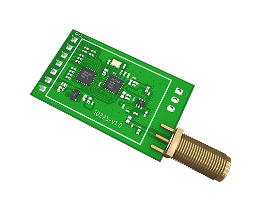
| Modulation | LoRa | New generation LoRa modulation technology |
| Communication interface | UART | TTL level |
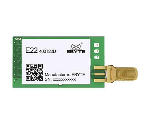
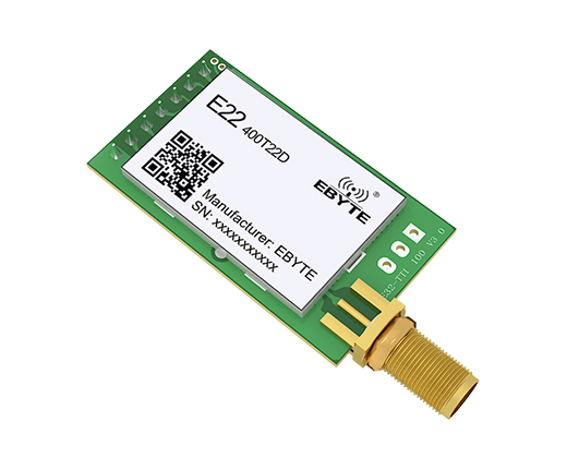
| Package | DIP | - |
| Connector | 1*7*2.54mm | - |
| Size | 21*36 mm | - |
| Antenna | SMA | 50 ohm impedance |

| No. |
Name |
Direction |
Function |
| 1 | M0 | Input(weak pull-up) | Work with M1 to decide 4 working modes of module (not suspended, if not used, could be grounded). |
| 2 | M1 | Input(weak pull-up) | Work with M0 to decide 4 working modes of module (not suspended, if notused, could be grounded). |
| 3 | RXD | Input | TTL UART input, connects to external TXD output pin. |
| 4 | TXD | Output | TTL UART output, connects to external RXD input pin. |
| 5 | AUX | Output | To indicate module ’s working status & wakes up the external MCU. Duringthe procedure of self-check initialization, the pin outputs low level. |
| 6 | VCC | Power supply | Module power supply positive reference, voltage range: 2.3 ~ 5.5V DC |
| 7 | GND | Power supply | Ground |
| 8 | Fixed hole | - | Fixed hole(Connect to GND on the module) |
| 9 | Fixed hole | - | Fixed hole(Connect to GND on the module) |
| 10 | Fixed hole | - | Fixed hole(Connect to GND on the module) |